Comprehensive Guide to Understanding the Cooling System Diagram in Black Tone
Welcome to a deep dive into the intricate world of automotive cooling systems. In this guide, you'll learn how to read and interpret a black-tone diagram of a car's cooling system, understand each component’s role, and see how they work together to keep your engine running smoothly. Whether you're a seasoned mechanic or just an automotive enthusiast, this article will provide clear explanations, visual references, and practical insights.
1. Overview of the Cooling System Diagram
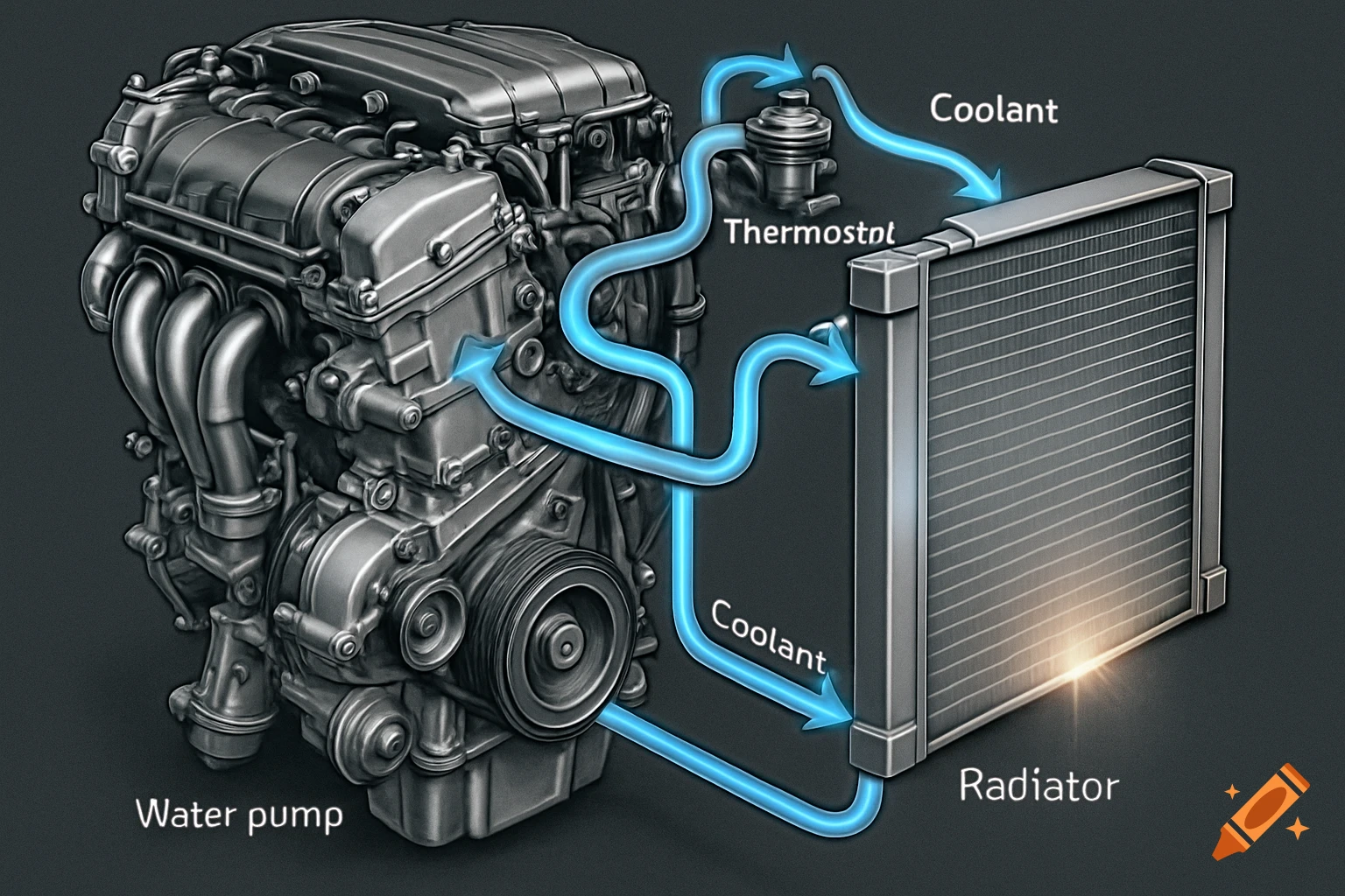
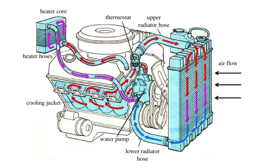
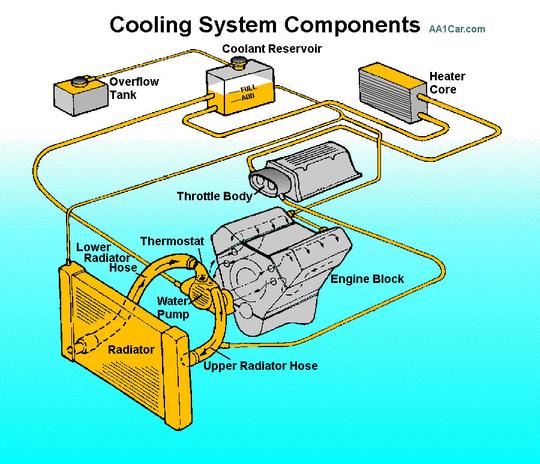
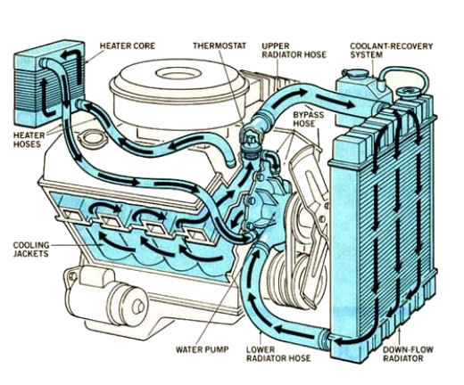
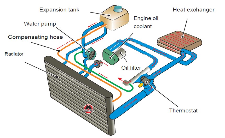
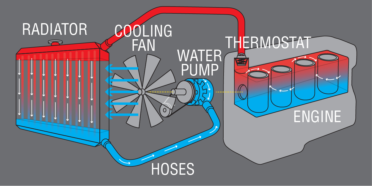
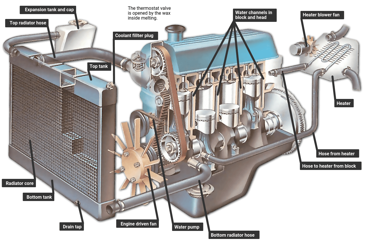
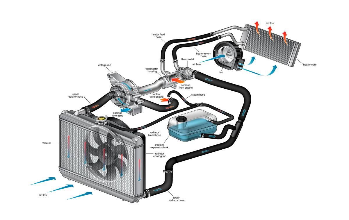
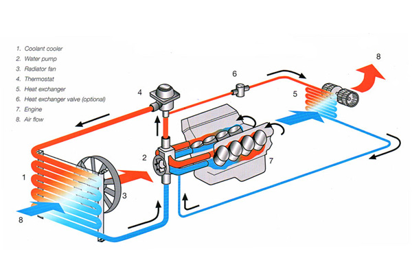
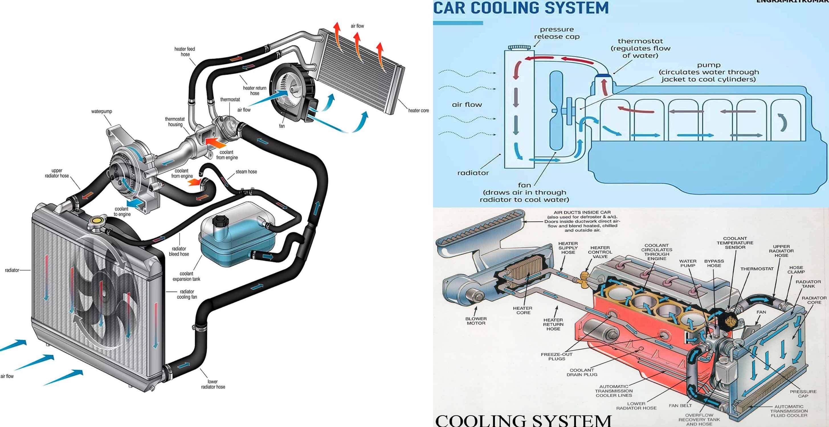
The cooling system diagram is a visual representation that outlines all the major parts involved in regulating engine temperature. In black tone, the diagram uses high-contrast shading to highlight each component, making it easier to distinguish the flow paths and component interactions. Key elements such as the radiator, water pump, thermostat, heater core, and coolant reservoir are depicted with distinct labels and color-coded arrows indicating coolant movement.

2. Water Pump: The Engine’s Lifeline
The water pump, often positioned at the front of the engine block, circulates coolant throughout the system. Its rotating impeller pushes the coolant through the engine’s passages, ensuring consistent temperature regulation. In the diagram, the pump is shown as a circular icon with arrows indicating the direction of flow. A key note in a black-tone diagram is the pump’s bearing condition; a worn bearing can lead to a drop in coolant pressure and potential overheating.
3. Thermostat: Temperature Gatekeeper
The thermostat regulates engine temperature by opening and closing based on coolant temperature. When the engine is cold, the thermostat remains closed, forcing coolant to circulate through the engine block to heat up. Once the coolant reaches a predetermined temperature, the thermostat opens, allowing coolant to flow into the radiator for cooling. The black-tone diagram uses a simple closed‑loop representation around the thermostat, with a small icon depicting the valve opening at a specific temperature.
4. Radiator: The Heat Exchanger
Radiators are the primary heat exchangers in the cooling system. They consist of a series of thin metal tubes that conduct heat away from the coolant, dissipating it into the air flowing through the radiator fins. In black-tone diagrams, the radiator is often shown as a rectangular block with parallel lines inside, representing the tubes, and arrows indicating coolant flow from the engine to the radiator and back. Proper airflow is crucial; a blocked radiator can significantly impair cooling performance.
5. Heater Core: Dual Purpose Cooling
The heater core, located in the cabin’s HVAC system, also plays a part in the cooling loop. Coolant passes through the heater core to provide cabin heat during colder weather. In the diagram, the heater core is shown as a smaller radiator-like component within the dashboard area. It shares the same coolant but directs it to the HVAC system instead of the external radiator. Understanding its placement is vital for diagnosing cabin heating issues.
6. Coolant Reservoir: Overflow Protection
The coolant reservoir, sometimes called the expansion tank, serves as an overflow container to accommodate coolant expansion due to temperature changes. Its level indicator helps monitor coolant volume, ensuring the system remains adequately filled. In a black-tone diagram, the reservoir is often depicted as a separate vessel with a gauge icon, emphasizing its importance in maintaining pressure and preventing air pockets.
7. Flow Paths and Pressure Management
Coolant flow paths are denoted by arrows on the diagram. These arrows indicate the direction of coolant movement from the engine block, through the water pump, to the radiator, and back to the engine. A pressure cap sits on the radiator neck to regulate system pressure; higher pressure allows the coolant to boil at a higher temperature, improving efficiency. In black-tone diagrams, pressure lines are often highlighted with bold arrows to draw attention to the critical pressure points.
8. Common Troubleshooting Scenarios
Interpreting the diagram can help diagnose common cooling system issues:
- Radiator blockage: Look for missing or reversed arrows between the radiator and the heater core.
- Thermostat stuck closed: Identify a missing flow arrow from the engine to the radiator.
- Water pump failure: Notice a broken or missing arrow at the pump icon.
- Leaking reservoir: Observe a broken line around the reservoir indicating a leak.
By systematically reviewing the diagram, you can pinpoint the problematic area and take appropriate corrective action.
Conclusion
A black-tone cooling system diagram serves as a powerful tool for visualizing the complex interactions within a vehicle’s engine cooling network. By understanding each component’s role—from the water pump’s circulation to the radiator’s heat dissipation—you gain the ability to maintain, troubleshoot, and optimize your engine’s temperature control. Whether you’re performing routine maintenance or diagnosing a persistent overheating issue, this guide equips you with the knowledge to interpret the diagram accurately and keep your car running at optimal temperatures.
Understanding The Engine Cooling System Diagram: A Comprehensive Guide

Understanding the Engine Cooling System Diagram: A Comprehensive Guide
Car Radiator Cooling System Diagram

Car Radiator Cooling System Diagram
Cooling System - Labelled Diagram

Cooling system - Labelled diagram
Schematic Diagram Of A Conventional Cooling System [2]. | Download
Schematic diagram of a conventional cooling system [2]. | Download ...
Engine Cooling System Diagram | Understanding Car Engine Functions, Car

Engine Cooling System Diagram | Understanding car engine functions, Car ...
Internal Combustion Engine Cooling System – VINQ

Internal Combustion Engine Cooling System – VINQ
A Visual Guide To How A Cooling System Works

A Visual Guide to How a Cooling System Works
Auto Cooling System Diagram
Auto Cooling System Diagram
Schematic Of The Engine Cooling System To Be Modeled | Download

Schematic of the engine cooling system to be modeled | Download ...
Cooling System
Cooling System
Basic Engine Cooling System At Carroll Zabala Blog

Basic Engine Cooling System at Carroll Zabala blog
Engine Cooling System Diagram | Car Anatomy

Engine Cooling System Diagram | Car Anatomy
Engine Cooling Diagram
Engine Cooling Diagram
Cooling System Diagram For Car Mechanics | Automotive Cooling System

Cooling System Diagram for Car Mechanics | Automotive cooling system ...
Car Radiator Cooling System Diagram

Car Radiator Cooling System Diagram
Engine Cooling Diagram
Engine Cooling Diagram
Car Engine Cooling System Diagram

Car Engine Cooling System Diagram
A Visual Breakdown Of The Ford 4.6 Cooling System

A visual breakdown of the Ford 4.6 cooling system
What Is A Cooling System? Its Diagram And How It Works

What Is A Cooling System? Its Diagram and How It Works
Understanding Your Auto Cooling System: A Comprehensive Diagram

Understanding Your Auto Cooling System: A Comprehensive Diagram
How Engine Cooling System Works?

How Engine Cooling System Works?
How An Engine Cooling System Works | How A Car Works
How an engine cooling system works | How a Car Works
Engine Cooling Diagram
Engine Cooling Diagram
Cooling System Diagram With Labels | Diesel Engine Components Diagram

Cooling System Diagram with Labels | Diesel engine components diagram ...
Cooling Systems – Bowen Hills Exhaust & Car Care
Cooling Systems – Bowen Hills Exhaust & Car Care
How Does Cooling System Work In Engine - Infoupdate.org
How Does Cooling System Work In Engine - Infoupdate.org
A Clear Blueprint: Understanding The Coolant System Diagram

A Clear Blueprint: Understanding the Coolant System Diagram
Automotive Cooling System Infographic Diagram Showing Process.. Royalty

Automotive Cooling System Infographic Diagram Showing Process.. Royalty ...
Cooling System Components | FridayParts

Cooling System Components | FridayParts