Understanding Cathodic Protection Diagrams: A Comprehensive Guide for Asian Oilfield Professionals
In this guide you will learn how to read, interpret, and apply cathodic protection diagrams to protect critical offshore and onshore infrastructure. You’ll discover the fundamental concepts, key components, common diagram types, and best practices tailored to the Asian oil and gas industry.
Basic Principles of Cathodic Protection
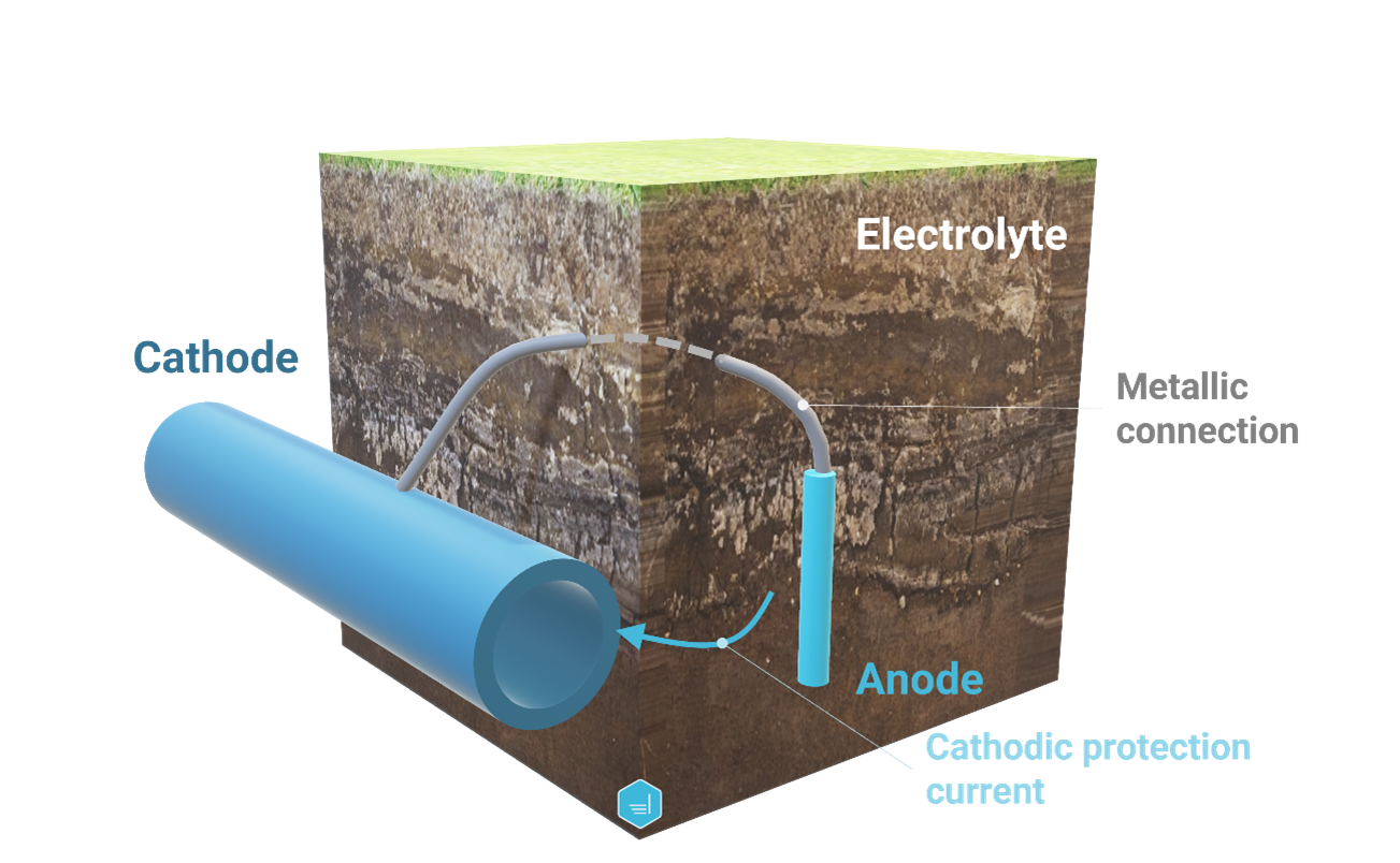
Cathodic protection (CP) is a passive corrosion control technique that uses an electrochemical potential to keep metal structures in a reduced state. By introducing a more negative electrode (the anode) or by applying an external current, the metal surface becomes the cathode of an electrochemical cell, preventing oxidation. The efficiency of a CP system hinges on accurate voltage and current distribution, which is clearly depicted in a CP diagram. Understanding these principles is essential before diving into diagram interpretation.
Components of a Cathodic Protection System
A standard CP system consists of several core components:
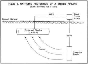
- Metal Structure (Cathode) – The pipeline, storage tank, or subsea cable that requires protection.
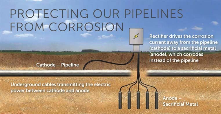
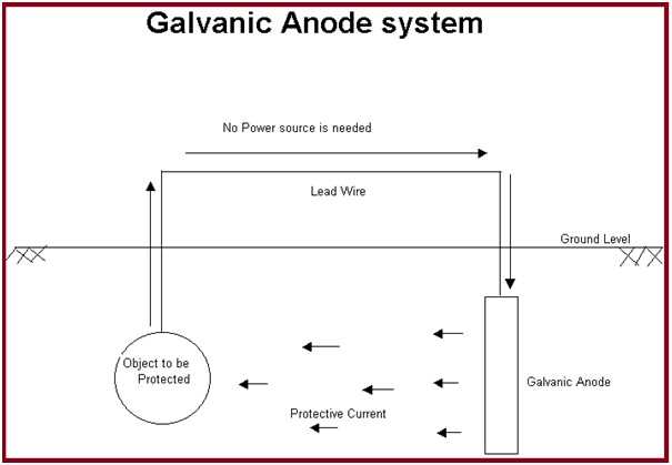
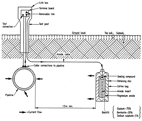
- Anodes – Sacrificial anodes (e.g., zinc, aluminum) or impressed current anodes (e.g., titanium-coated steel) that supply electrons to the cathode.
- Electrical Connections – Insulated cables and terminals that link anodes to the structure.
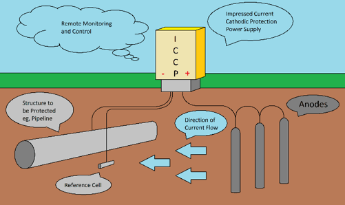
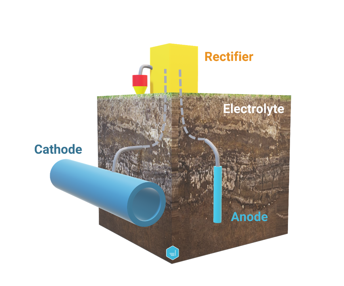
- Control Unit – For impressed current systems, a rectifier or inverter regulates voltage and monitors performance.
– Potentiostats, voltage sensors, and data loggers that track system health.
The diagram below demonstrates how these components interconnect and how voltage gradients are established across the structure.
Interpreting the Diagram
When reading a CP diagram, look for the following key indicators:
- Voltage Distribution – Often shown as a gradient or color map indicating potential differences.
- Anode Placement – Spatial coordinates of anodes relative to the structure’s geometry.
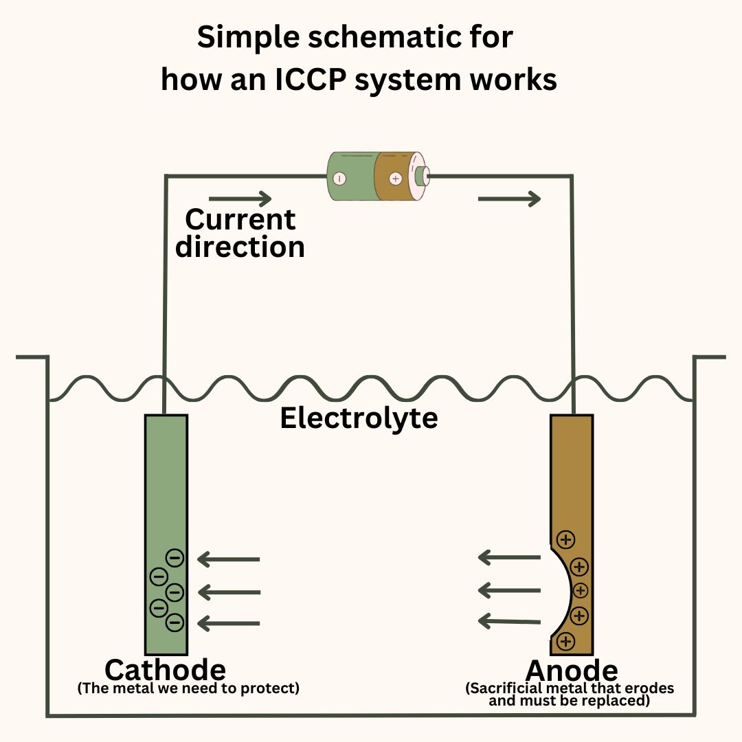
- Current Path – Arrows or lines that show electron flow direction.
- Environmental Factors – Symbols indicating soil resistivity, water chemistry, or temperature zones.
By cross-referencing the diagram with field data, engineers can validate the adequacy of protection and make informed adjustments.
Common Types of Diagrams
There are several diagram formats used across the industry:
- Plan View Diagram – A top-down representation, ideal for pipelines and tanks.
- Sectional View – Shows vertical relationships, useful for offshore platforms.
- Electrical Schematic – Focuses on current flow and control electronics.
- Simulation Graph – Generated by finite element analysis tools to predict potential distribution.
The illustration below provides a clear example of cathodic protection fundamentals, including key parameters like resistance, voltage, and current density.

Practical Application in Asian Oilfields
Asian oilfields present unique challenges such as high salinity, fluctuating water tables, and diverse geological formations. Effective CP deployment requires:
- Local Soil and Water Testing – Accurate resistivity measurements guide anode sizing.
- Compliance with Regional Standards – Many Asian countries adopt the ISO 15140 series and local codes for CP.
- Integration with Digital Twins – Real-time data feeds into a virtual model for predictive maintenance.
- Training and Knowledge Transfer – Continuous education for local technicians ensures system longevity.
By following these steps, operators can achieve consistent protection levels, reduce maintenance costs, and extend asset life.
Maintenance & Troubleshooting
Routine inspections are vital. Key actions include:
- Checking anode integrity and replacing corroded units.
- Monitoring voltage between anode and cathode to stay within design limits (usually -0.2 V to -0.5 V).
- Inspecting cable insulation and connector integrity.
- Updating simulation models with latest field data.
When anomalies arise, such as unexpected voltage spikes or anode depletion, refer back to the diagram to verify the current paths and potential distribution. Adjustments can often be made by repositioning anodes or tweaking the control unit setpoints.
Future Trends in Cathodic Protection
Emerging technologies are reshaping CP strategy:
- Smart Anodes – Sensors embedded in anodes provide real-time status.
- AI-Driven Diagnostics – Algorithms analyze large datasets to predict failure points.
- Renewable Power Sources – Solar and wind-driven CP units reduce reliance on diesel generators.
- Advanced Materials – High-efficiency anode coatings extend service life by up to 30%.
Staying ahead of these innovations ensures that Asian operators maintain a competitive edge in corrosion management.
Conclusion
Mastering cathodic protection diagrams empowers engineers to design, implement, and maintain robust corrosion protection systems. By understanding the basic principles, interpreting key diagram elements, and applying best practices tailored to Asian oilfield conditions, you can safeguard critical assets and optimize operational reliability. Continuous learning and integration of modern technologies will further enhance system performance and sustainability.
Cathodic Protection Criteria | Protection Cathodique C’Est Quoi – SCLH

Cathodic Protection Criteria | Protection Cathodique C’Est Quoi – SCLH
What Is Cathodic Protection?

What is cathodic protection?
Passive And Active Cathodic Protection - Pietro Fiorentini

Passive and active cathodic protection - Pietro Fiorentini
Schema Of Cathodic Protection (left) And Cathodic Polarization (right
Schema of cathodic protection (left) and cathodic polarization (right ...
Cathodic Protection: Definition, Working Principles, Types, Design
Cathodic Protection: Definition, Working Principles, Types, Design ...
ENGCORR | Cathodic Protection

ENGCORR | Cathodic Protection
Diagram Of Impressed Current Cathodic Protection. | Download Scientific
Diagram of impressed current cathodic protection. | Download Scientific ...
Cathodic Protection
Cathodic Protection
Why Magnesium Anodes Are Used As Sacrificial Cathodic Protection

Why Magnesium Anodes Are Used As Sacrificial Cathodic Protection ...
Schematic Showing Cathodic Protection Methods Using Sacrificial Anode
Schematic showing cathodic protection methods using sacrificial anode ...
Cathodic Protection Well Standards
Cathodic Protection Well Standards
Cathodic Protection System

Cathodic Protection System
Cathodic Protection | Metallurgy For Dummies
Cathodic Protection | Metallurgy for Dummies
An Overview Of The Basic Terms And Terminology Used In Cathodic
An overview of the basic terms and terminology used in cathodic ...
Cathodic Protection

Cathodic Protection
Cathodic Protection For Ships - All You Need To Know
Cathodic Protection for Ships - All you need to know
What Is Galvanic Cathodic Protection
What Is Galvanic Cathodic Protection
Pipe Cathodic Corrosion Protection: Definition And Uses – ESAin - Esain
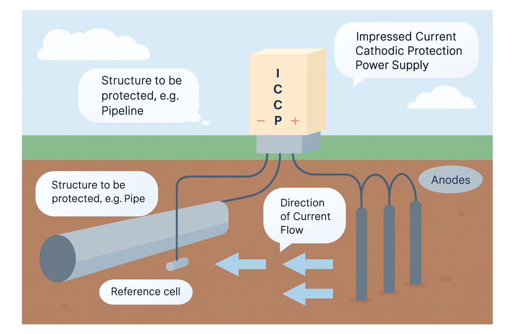
Pipe Cathodic Corrosion Protection: Definition and Uses – ESAin - Esain
Impressed Current Cathodic Protection Working Principle At Renee

Impressed Current Cathodic Protection Working Principle at Renee ...
Cathodic Protection Systems Thailand | JST Group

Cathodic Protection Systems Thailand | JST Group
Induced Current Cathodic Protection – TVHG

Induced Current Cathodic Protection – TVHG
How Cathodic Protection System Working |Types |Application - YouTube
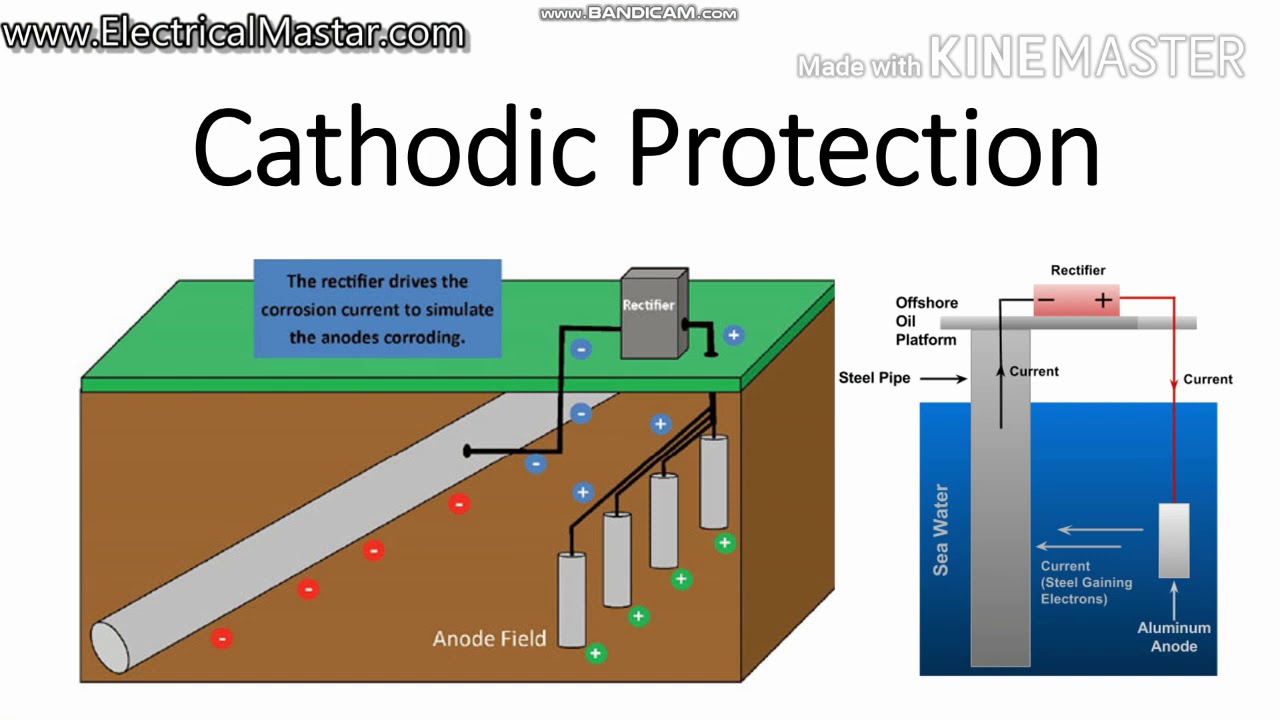
How Cathodic protection system working |Types |Application - YouTube
IMPRESSED CURRENT CATHODIC PROTECTION | PPTX
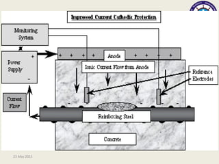
IMPRESSED CURRENT CATHODIC PROTECTION | PPTX
Cathodic Protection (CP) Systems Used To Protect Metal Structures From

Cathodic protection (CP) systems used to protect metal structures from ...