Diagram of a DC Motor: A Comprehensive Guide
In this guide you will gain a clear understanding of how a DC motor diagram conveys the essential components, electrical connections, and mechanical operation of the device. You will learn how to read the labeled parts, interpret the direction of current flow and rotation, recognize common variations, and avoid typical misconceptions that arise when studying DC motor schematics.
Overview of DC Motor Components
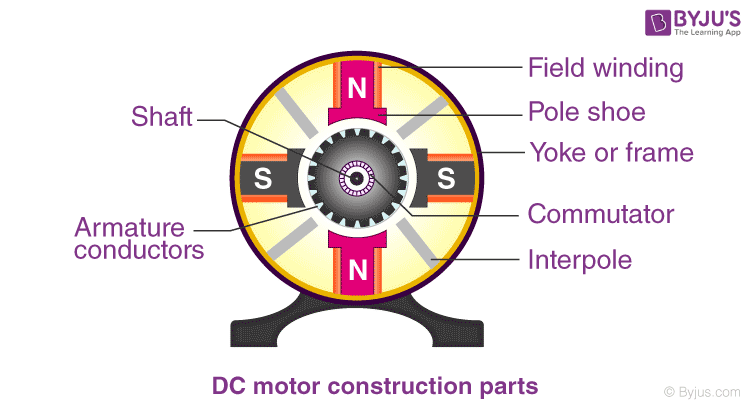
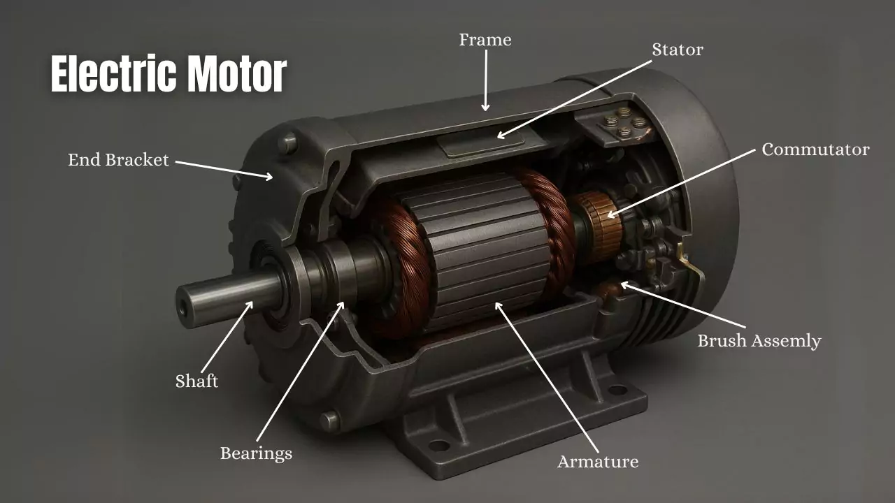
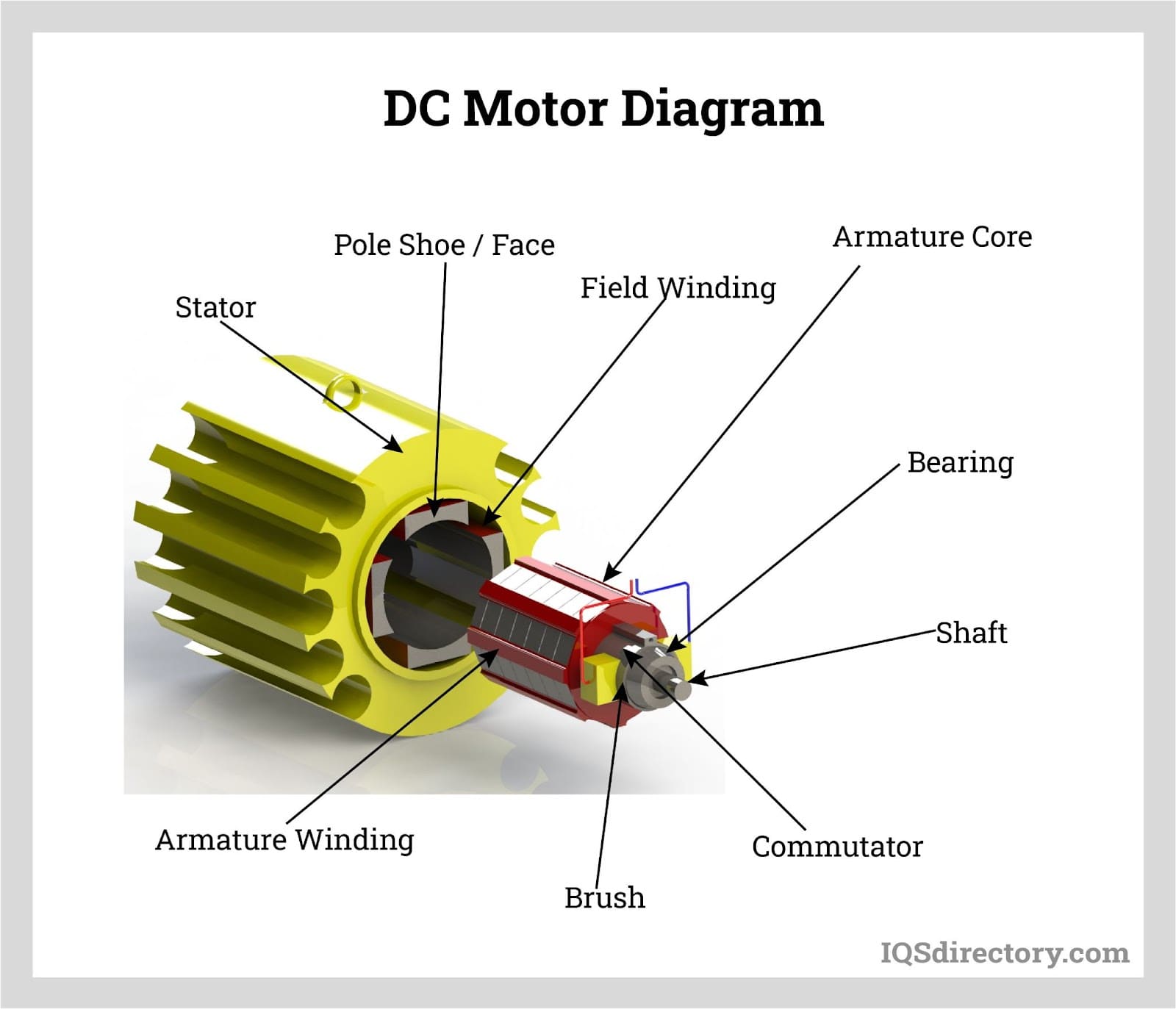
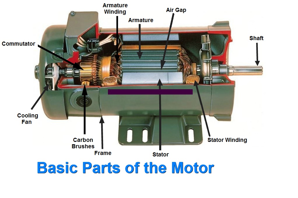
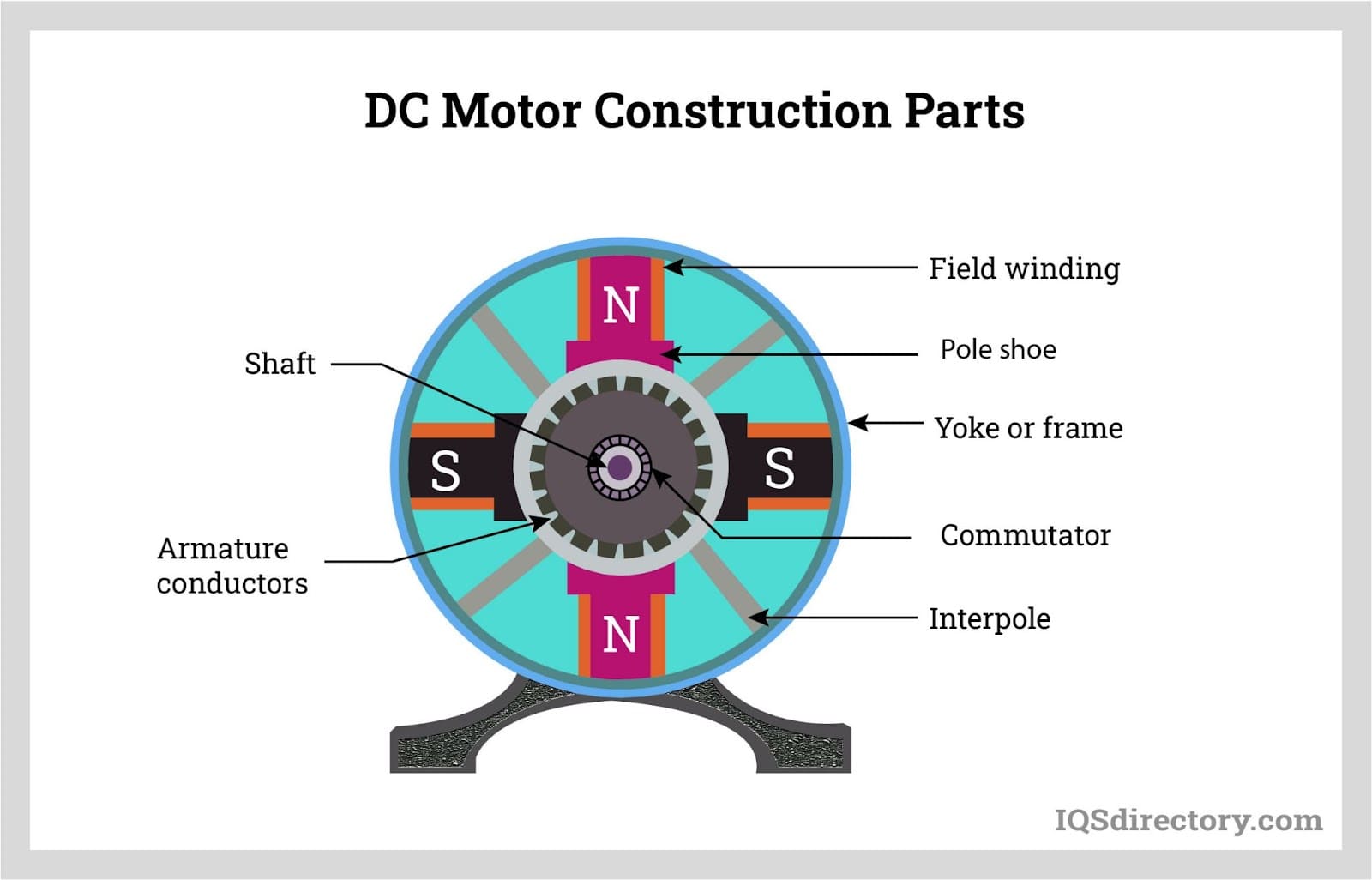
A DC motor is fundamentally a conversion machine that turns electrical energy into mechanical motion. The basic components—stator, rotor (armature), commutator, brushes, and field windings—work together to produce a continuous torque. In a typical diagram, these parts are shown as a series of labeled symbols and physical shapes: the stator as a stationary housing, the rotor as a cylindrical shaft with windings, the commutator as a segmented ring, and the brushes as flat conductive pads that make sliding contact. Each component is illustrated with a distinct shape so that its function can be instantly recognized.
How the Diagram Illustrates Motor Operation
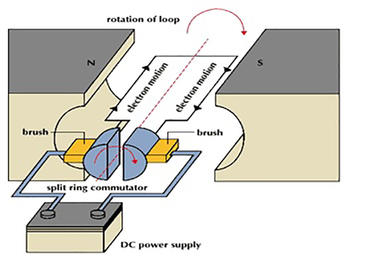
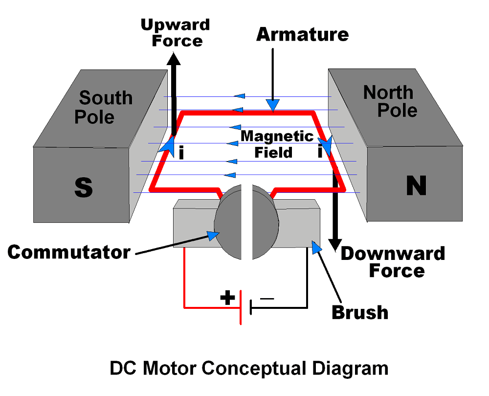
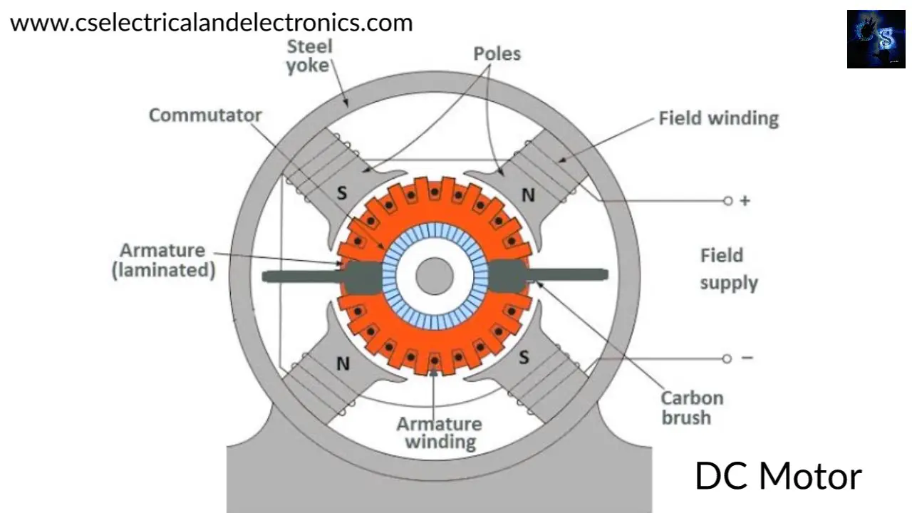
The diagram uses arrows to show the path of current through the armature windings and the resulting magnetic fields. By following these arrows, you can see how the interaction between the stator field and the rotating armature produces a torque that spins the shaft. The labeled arrows also indicate the direction of magnetic flux, which is essential for understanding the polarity of the motor. When combined with the commutator and brush symbols, the diagram demonstrates how electrical switching is achieved mechanically, allowing the armature to maintain continuous rotation.
Key Parts and Their Functions
- Stator: Provides the fixed magnetic field. In some designs, permanent magnets are used; in others, electromagnets generate the field.
- Rotor (Armature): Contains windings that carry current. When exposed to the stator’s magnetic field, it experiences a torque.
- Commutator: A segmented cylindrical switch that reverses the current direction in the rotor windings each half‑turn, ensuring continuous torque.
- Brushes: Conductive carbon or metal contacts that press against the commutator, delivering current from the external circuit.
- Field Windings: Optional coils that create the magnetic field in wound-field motors. Their current can be varied to control motor speed.
- Bearings: Support the shaft and reduce friction, allowing smooth rotation.
Each of these components is depicted in the first image, which shows the parts of a DC motor in a stylized format. The illustration helps readers visualize the spatial relationship between the rotating and stationary parts.
Understanding the Polarity and Current Flow
Polarity is indicated by the placement of positive (+) and negative (–) signs near the input terminals. The direction of the arrow on the current flow lines is critical: reversing the polarity of the applied voltage will reverse the direction of rotation. A correctly drawn diagram will show that the current enters one brush, traverses the armature winding, and exits through the commutator segment before reaching the opposite brush. This cyclic path is the essence of DC motor operation, as it ensures that the torque remains in the same rotational sense even as the commutator switches the current direction.
Variations in DC Motor Diagrams
There are several variations of DC motor diagrams you will encounter in literature:
- Simple Brushless DC Motor (BLDC) Schematics: These omit commutator and brush symbols, focusing on electronic speed controllers and permanent magnets.
- Three‑Phase DC Motor Diagrams: Though rare, some industrial motors use a three‑phase supply, resulting in multiple sets of windings and phase arrows.
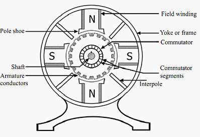
- Cross‑Sectional Views: Detailed cross‑sections show internal winding patterns and the commutator’s segment structure, giving deeper insight into construction.
- Electrical Symbol Diagrams: These use standardized circuit symbols for the motor’s electrical connections, suitable for schematic capture in PCB design.
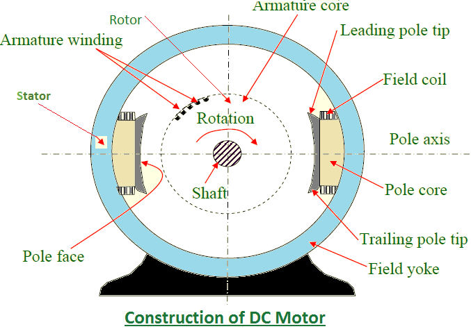
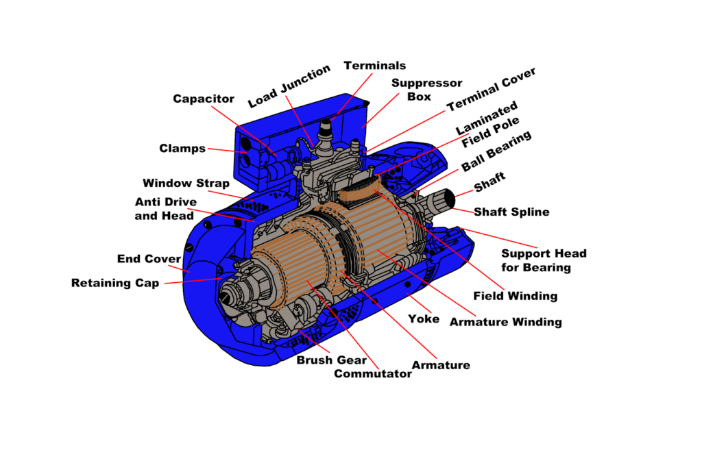
The second image in the provided data is a labeled diagram that captures many of these variations. It illustrates the entire assembly with arrows, field lines, and labeled components, offering a practical reference for students and engineers alike.

Common Misconceptions
One frequent misunderstanding is the belief that a DC motor’s rotation can be halted simply by removing one brush. In reality, the commutator requires both brushes for proper switching; removing one disrupts the current path and may damage the motor. Another misconception involves the field strength: some assume that increasing the field current always increases torque. While true up to the magnetic saturation point, exceeding that limit can actually reduce efficiency and increase heating.
Conclusion
Mastering the interpretation of a DC motor diagram is a foundational skill for anyone working with electromechanical systems. By identifying each component, following the current paths, and understanding how polarity governs rotation, you can troubleshoot motor behavior, design efficient control circuits, and predict performance under varying loads. Equipped with the visual references and detailed explanations provided here, you now have the knowledge to read any DC motor schematic confidently and apply it to real‑world engineering challenges.
Parts Of A Dc Motor Diagram

Parts Of A Dc Motor Diagram
What Is Dc Motor With Diagram At Kristin Morton Blog

What Is Dc Motor With Diagram at Kristin Morton blog
Brushed Dc Motor 14 Download Scientific Diagram Concentrated Winding

Brushed Dc Motor 14 Download Scientific Diagram Concentrated Winding
DC Motor - Definition, Working, Types, And FAQs

DC Motor - Definition, Working, Types, and FAQs
Basic Dc Motor Circuit Diagram

Basic Dc Motor Circuit Diagram
Working Principal Of DC Motor: Construction Of DC Motor
Working principal of DC Motor: Construction of DC Motor
Basic Dc Motor Circuit Diagram

Basic Dc Motor Circuit Diagram
Types Of DC Motors

Types of DC Motors
What Are The Main Parts Of A DC Motor And How Do They Work - AIChipLink
What Are the Main Parts of a DC Motor and How Do They Work - AIChipLink
What Are The Main Parts Of A Dc Motor At Hayden Seton Blog

What Are The Main Parts Of A Dc Motor at Hayden Seton blog
Electric Motor Diagram For Kids

Electric Motor Diagram For Kids
Dc Motor Car Diagram
Dc Motor Car Diagram
Draw A Labelled Diagram Of DC Motor.
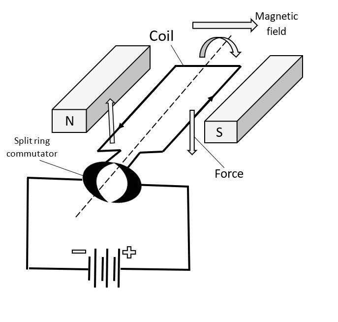
Draw a labelled diagram of DC motor.
Parts Of A Dc Motor Diagram At Pamula Hilson Blog

Parts Of A Dc Motor Diagram at Pamula Hilson blog
3 Model Of A Brush Dc Motor Download Scientific Diagram Commutator
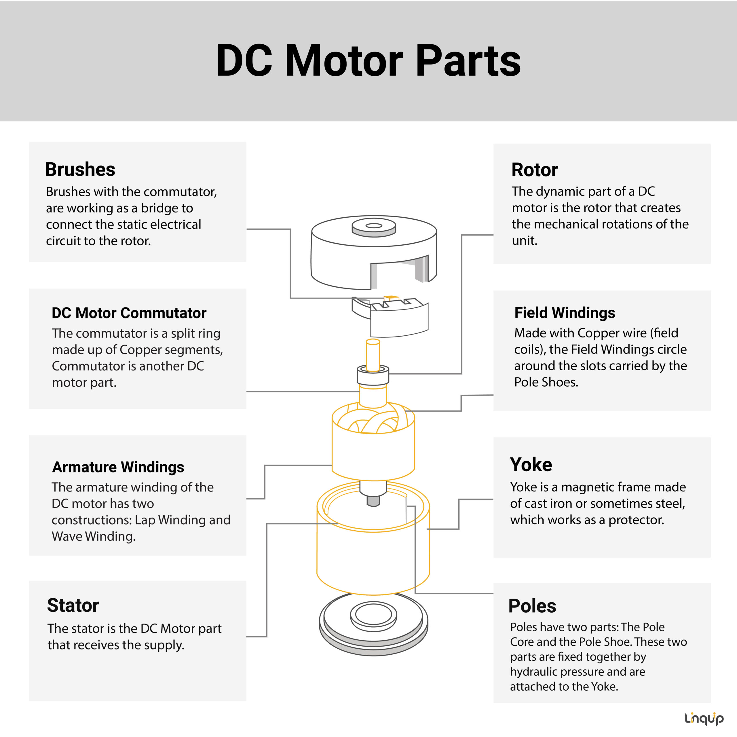
3 Model Of A Brush Dc Motor Download Scientific Diagram Commutator
Dc Motor Circuit Diagrams
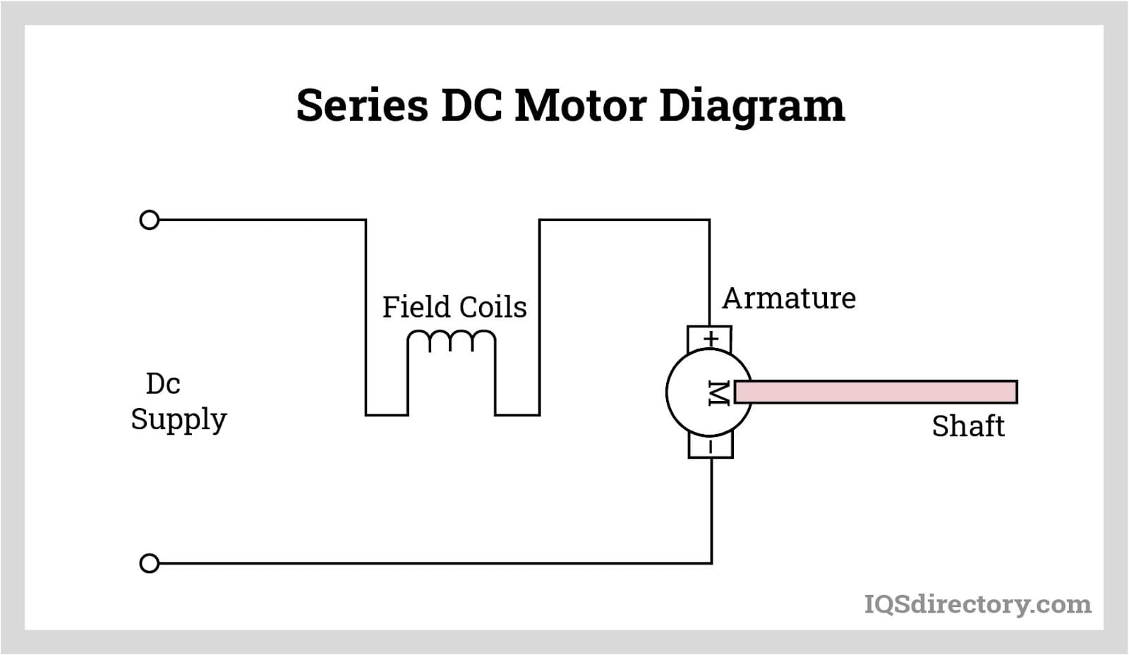
Dc Motor Circuit Diagrams
Types Of DC Motors, Their Working Principle And Applications

Types of DC Motors, Their Working Principle and Applications
Basic Dc Motor Circuit Diagram
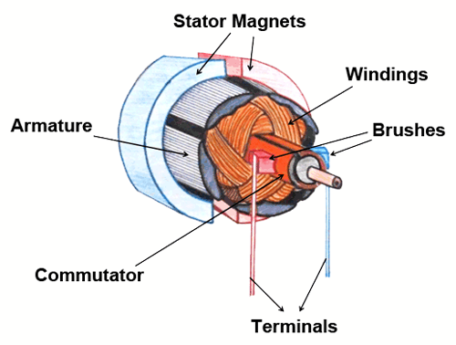
Basic Dc Motor Circuit Diagram
A Visual Guide To Understanding DC Motor Schematic Diagrams

A Visual Guide to Understanding DC Motor Schematic Diagrams
Electric Motor Diagram And Explanation At Donald Lyman Blog
Electric Motor Diagram And Explanation at Donald Lyman blog
Dc Motor Full Form , DC Motor: Definition, Diagram, Construction
Dc Motor Full Form , DC Motor: Definition, Diagram, Construction ...
Anatomy Of A DC Motor: Understanding The Diagram

Anatomy of a DC Motor: Understanding the Diagram
Dc Motor Structure Diagram Dc Motor Diagram And Construction
Dc Motor Structure Diagram Dc Motor Diagram And Construction
Basics Of DC Motors: An Introduction To DC Motors, Their Working

Basics of DC Motors: An Introduction to DC Motors, Their Working ...
Basic Dc Motor Circuit Diagram
Basic Dc Motor Circuit Diagram
DC Motor Diagram And Constructional Parts - ETechnoG

DC Motor Diagram and Constructional Parts - ETechnoG
Basic Dc Motor Circuit Diagram
Basic Dc Motor Circuit Diagram
Dc Motor Working Principle And Construction With Diagram Explanation

Dc motor working principle and construction with diagram explanation ...
What Is Dc Motor? Diagram _ Dc Motors Explained – YOFR
What Is Dc Motor? Diagram _ Dc Motors Explained – YOFR
Dc Motor Circuit Diagrams
Dc Motor Circuit Diagrams
DC Motor Brushes Complete Guide | JAST POWER

DC Motor Brushes Complete Guide | JAST POWER